Hangzhi Precision

How to Use Hangzhi Fluxgate Current Transducers

1. How to use AIT high precision current transducers

1.1 How to wire AIT high precision current transdudcer

how to use AIT high precision current transducer

1.2 How to measure with AIT high precision current transdudcer

Important Note:

The resistance connected to the output terminal of the sensor should be within the range specified in the datasheet.

(a) When the sensor does not pass current, the voltage on the resistor R is about 0V
(b) When the device is working normally after power on, the green indicator light is always on
(c) When the sensor passes a DC current, the voltage on the resistor R is:
U = Measured Current / Sensor Turns Ratio * Resistance R

If the output voltage is abnormal:

(a) First use a multimeter to measure the power supply of the sensor and check whether the power supply is wired correctly;

(b) Check whether the running indicator and the power supply indicator are displayed normally.

2. How to use HIT hall-effect replacement and IIT industrial current transducers

2.1 How to wire HIT & IIT current transdudcer

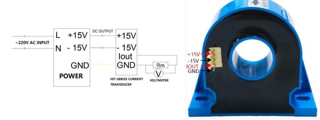
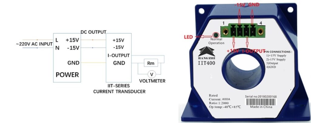
The wiring method of the HIT and IIT current transducer is almost the same, please find the details below:

However, there is no operation indicate LED on HIT current transducers. 

2.2 How to measure with HIT hall-effect replacement current transdudcer

(2) Test method: 
The resistance connected to the output terminal of the sensor should be within the range specified in the datasheet. 

When the wiring is correct and working normally:
(a) When the sensor does not pass current, the voltage on the resistor Rm is about 0V;
(b) When the sensor passes a DC current, the voltage on the resistor Rm is:
U = Measured Current / Sensor Turns Ratio * Resistance Rm


3. How to use RIT leakage current transducers

3.1 How to wire RIT leakage current transdudcer

3.2 How to measure with RIT leakage current transdudcer

(2) Test method: 
The output terminal of the sensor is connected to the voltage meter or analogical input module

When the wiring is correct and working normally:
(a) When the primary current is 0A, the output voltage of the sensor is about 0V;
(b) After the device is powered on, when the device is working normally, the green indicator light is always on;
(c) When the sensor passes DC current, the primary current Ip is:
Ip=Kn*Uoutput

If the current is abnormal or the power supply is abnormal:
(a) First use a multimeter to measure the power supply of the sensor and check whether the power supply is wired correctly;

en_USEnglish